
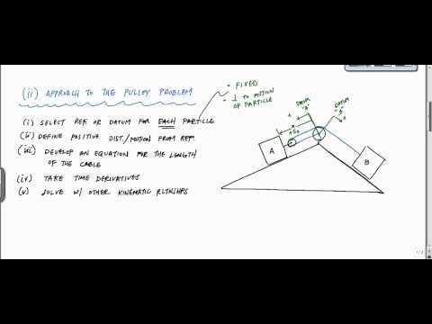
You will not need to include this length of cord in the dependent motion equation. For equation 4 if particle A’s acceleration shares the same direction as its velocity than the particle is accelerating, if the signs are opposite than the particle is decelerating. Also, if one particle is accelerating than the other particle is also accelerating, while if one particle is decelerating than the other particle also has to decelerate. To determine how far each particle will move you will need to determine the length of the chord. You will need to find the length $S_A$ as well as the length $S_B$. To find the relationship of these two lengths use the equation below. In the image above the lengths $s_A$ and $s_B$ are dependent on the positions of particle A and particle B.
I demonstrate a directional motion-transmission behavior of aligned carbon nanotubes using atomistic simulations. The network of overlapping $\pi$ orbitals at the interface act as gear teeth to translate the sliding motion of a CNT into a rotating motion of the adjacent CNT, or \textit. The efficiency of this orthogonal motion transmission is found to strongly depend on the tube chirality, by which the interfacial stacking configuration of the atoms is determined.
These results have strong implications on the design of the motion transmission system at the nanoscale. Now that we have done a careful derivation, we should be able to more quickly derive constraint equations, e.g. The linear time-dependent motion of a floating elastic or rigid body, subject to some initial displacement, which subsequently evolves freely is considered.
This represents the length of the cord that is making contact with the pulley. A pulley will normally always have a constant diameter, which mean $l_$ will not change.
These two modes of motion exhibited by the clusters were rotation and oscillation, depending on the size of the cluster. Due to the interaction between the rotating magnetic field and the net magnetic dipole moment, the clusters were subjected to a forced vibration. A critical diameter range for the magnetic clusters was defined that may be used to distinguish between the rotation and oscillation of clusters. Furthermore, the characteristics of size dependence of the clusters’ motion were also investigated. You must be signed into an individual account to use this feature.
The Time
The way in which the motion of these particles is connected is known as the constraint. A simple example of a constrained system is shown in the image below. Imagine a pickup truck gets stuck in the sand, and a friend uses a rope to help pull them out.

For example if you had two objects connected to each other through a cord their motion would be dependent on each other. You could further this example by wrapping the cord around a pulley or a series of pulleys as seen in the image below. •Efficient formulas for the time dependent motion of a floating rigid or elastic body, which require only the frequency domain solution and no time-stepping, are given. Finally, you can find the acceleration of the two particles by taking the derivative of equation 3 or the double derivative of equation 2 in respect to time. Next, if you want to find the the velocity of the two particle you will need take the derivative of equation 2 in respect to time. Realize that the the length of cord does not change in respect to time, so you will not need to include that in the equation.
Sign Up For Article Alerts
A series of new identities for the frequency-domain problem are also presented. The Fourier transform solution allows an approximate solution to be calculated by an expansion over the complex resonances known as the singularity expansion method.
‘@free.kindle.com’ emails are free but can only be sent to your device when it is connected to wi-fi. ‘@kindle.com’ emails can be delivered even when you are not connected to wi-fi, but note that service fees apply.
We used a Kanitzsa illusory rectangle as a pursuit target (6°×8°), with the four gray inducers presented at high (100 cd/m2) or low luminance (1 cd/m2) on a yellow bright background (100cd/m2). Subjects tracked the center of the illusory target during a motion ramp at 8°/s. At an unpredictable time the inducers changed luminance for 500ms and then reverse back. We found that the effect of luminance-contrast on steady-state pursuit gain was stronger during the luminance change transitions than with constant luminance.
Simple expressions for the singularity expansion method approximation are given. The method is illustrated with a series of numerical calculations. The network of overlapping π orbitals at the interface act as gear teeth to translate the sliding motion of a CNT into a rotating motion of the adjacent CNT, or viceversa.
An easy way to demonstrate this concept is to use examples involving particles connected by “inelastic” cords and pulleys. It is these connections that provide the constraint equations necessary to relate the motion of one particle relative to another. Dependent motion analysis is used when two or more particles have motions that are in some way connected to one another.
Coherently, smooth tracking of low-contrast stimuli is impared both during pursuit initiation (longer latency, Spering et al., 2005) and steady state . Importantly, smooth pursuit data allows one to reliably track fine details of the dynamic modulations of visual processing across time.
During the transition, two uniform film regions coexist, separated by a step-like transitional region. The transitional motion also requires modification of the film solution near the rear of the bubble, which depends on the ratio of the two capillary numbers. These theoretical results are verified by experiments and numerical simulations. The lengths of cord that will change are between point CE, ED, and DB. CE and ED will have the same length $s_A$, while DB will have a length of $s_B$. The length of cord will not change between points A and E.
Article Contents
We investigate the dynamics of structured photoactive microswimmers and show that morphology sensitively determines the swimming behavior. Particular to this study, a major portion of the light-activated particles’ underlying structure is built from a photocatalytic material, made possible by dynamic physical vapor deposition . We find that swimmers of this type exhibit unique shape-dependent autonomous swimming that is distinct from what is seen in systems with similar structural morphology but not fabricated directly from the catalyst. Notably, the direction of motion is a function of these parameters. Because the swimming behavior is strongly correlated with particle shape and material composition, DPVD allows for engineering small-scale propulsion by adjusting the fabrication parameters to match the desired performance.
- You will not need to include this length of cord in the dependent motion equation.
- The network of overlapping $\pi$ orbitals at the interface act as gear teeth to translate the sliding motion of a CNT into a rotating motion of the adjacent CNT, or \textit.
- In this work, we investigate how this steady state is established by considering the transitional motion of the bubble as it adjusts its film thickness profile between two steady states, characterized by two different bubble speeds.
- These results have strong implications on the design of the motion transmission system at the nanoscale.
- An easy way to demonstrate this concept is to use examples involving particles connected by “inelastic” cords and pulleys.
- For this typical participant, there is a strong positive relationship between the physical motion and reported motion.
2020.Experimental and analytical investigation of meso-scale slug bubble dynamics in a square capillary channel. This article has been cited by the following publications. If you should have access and can’t see this content pleasecontact technical support. Get access to the full version of this content by using one of the access options below. Clipping is a handy way to collect important slides you want to go back to later. Now customize the name of a clipboard to store your clips.
Understanding of the visual system can be informed by examining errors in perception. We present a novel illusion-Wandering Circles-in which stationary circles undergoing contrast-polarity reversals (i.e., flicker), when viewed peripherally, appear to move about in a random fashion. In two psychophysical experiments, participants rated the strength of perceived illusory motion under varying stimulus conditions.
Dependent Motion
We use cookies to help provide and enhance our service and tailor content and ads. Art pieces that ‘move’ in our minds–an explanation of illusory motion based on depth reversal. A two-frame display in which two dots occupy positions at the top left and bottom right points of an imaginary square at Time 1 and the top right and bottom left points Time 2 . Observers generally report that the dots appear to move between the two positions rather than simply appearing. At each position change, dots may be observed to move consistent with the interpretation presented in or that in . Likert ratings in response to real motion were modeled using logarithmic regression . This model was then used to estimate the physical equivalents of the perceived motion in the 9.44 reversals per second flickering stimuli for the Cornsweet , solid-line , and Gaussian conditions.
The solution is derived by a Fourier transform and by the generalized eigenfunction method. Compared to other solutions, such as the Cummins method, the present solution requires neither time-stepping nor high-frequency calculations.
You can simplify equation 1 by removing $l_ from equation 1.
To send this article to your Kindle, first ensure no- is added to your Approved Personal Document E-mail List under your Personal Document Settings on the Manage Your Content and Devices page of your Amazon account. Then enter the ‘name’ part of your Kindle email address below. Find out more about sending to your Kindle.Find out more about sending to your Kindle. When a confined bubble translates steadily in a cylindrical capillary tube, without the consideration of gravity effects, a uniform thin film of liquid separates the bubble surface and the tube wall. In this work, we investigate how this steady state is established by considering the transitional motion of the bubble as it adjusts its film thickness profile between two steady states, characterized by two different bubble speeds.
The illusory motion percept was strongest when the circle’s edge was defined by a light/dark alternation and when the edge faded smoothly to the background gray (i.e., a circular arrangement of the Craik-O’Brien-Cornsweet illusion). In addition, the percept of illusory motion is flicker rate dependent, appearing strongest when the circles reversed polarity 9.44 times per second and weakest at 1.98 times per second. In certain cases the motion of one particle could be dependent on the motion of another particle.
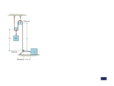
The first thing we will need to do when analyzing these systems is to come up with what is known as the constraint equation. A constraint equation will be some geometric relationship that will remain true over the course of the motion. Using the tree as a stationary point, we can also say that the length of the rope is the distance from the green car to the tree, plus two times the distance from the pickup truck to the tree . If we put this into an equation we would have the following. The underestimation of speed for low-contrast, slowly moving objects is a well established phenomenon.
For this typical participant, there is a strong positive relationship between the physical motion and reported motion. In contrast, for this participant, the solid lines exhibited less illusory motion and the Gaussians even less. Please also list any non-financial associations or interests that a reasonable reader would want to know about in relation to the submitted work. This pertains to all the authors of the piece, their spouses or partners. Your email address will be used in order to notify you when your comment has been reviewed by the moderator and in case the author of the article or the moderator need to contact you directly. By using this service, you agree that you will only keep articles for personal use, and will not openly distribute them via Dropbox, Google Drive or other file sharing services.Please confirm that you accept the terms of use. Note you can select to send to either the @free.kindle.com or @kindle.com variations.
This friend ties one end of the rope to the rear bumper of her car, loops the rope around a bar on the front of the pickup truck, then ties the other end to a stationary tree. In this case the two vehicles will not have the same velocity or acceleration, but their motions are related because they are tied together by the rope. In this case, the rope is acting as the constraint, allowing us to know the velocity or acceleration of one vehicle based on the velocity or acceleration of the other vehicle. See this example, which carefully derives the constraint equation for two particles connected by a system of pulleys and ropes. The motion of the car and the pickup truck will be related to one another via rope that is connecting them.
